SDRPlay Independent Community Forum › Forums › SDR Software (RSP Compatible) › Spectrum analyser software
Tagged: Data Dump Issues
- This topic has 30 replies, 11 voices, and was last updated by .
-
AuthorPosts
-
January 28, 2020 at 4:32 pm #610N1IXFParticipant
Great software and I’m beginning to learn to use it.
Wondering what a safe max power input to the RSP2Pro would be?
I wish to construct an attenuating tap to sample RF from a 100W transmitter. Should I use less than 0dBm as the target? What signal level would be preferred for best dynamic range?
Thanks and 73,
Rich N1IXFJanuary 29, 2020 at 1:36 am #613Steve AndrewParticipantHi Rich
Input to the RSP is 0dBm continuous and 10dB for short periods.
Dynamic range will for the most part be decided by selection of IF frequency.
Generally, the ADC will start to overload when the input signal reaches around 10-15dB higher than the reference level set on the analyser. 0dB input is OK but will leave you little room for error. It might be worth having a few in-line attenuators that can be used between the dummy load tap and the RSP if required. This would allow you to use a lower reference level setting, with the advantage of a lower noise floor.
Best regards
Steve
May 18, 2020 at 1:04 am #1008ELHandJrParticipantI constructed a -50DB attenuator and am using it with good results with an RSP1A. I still need another -20 DB to get good results. This is through a step attenuator so that I can adjust based on conditions.
I am very happy with the software and device.
Link to homebrew attenuator: http://www.ad5x.com/images/Articles/Tap50dbRevA.pdf
73
Evan
AC9TUJune 15, 2020 at 9:01 pm #1094DanParticipantI really like this new Version 1.1 of the Analyser – especially the .csv file output.
I am attempting to use the software for the ARRL Frequency Measuring Test, but I am having difficulty.
In short, the Test works like this — we are given a frequency to tune to to get us in the ballpark. Then, a station will transmit a tone close by (10-50 Hz +/-) for us to measure.I can get a peak showing on the unknown frequency, but if I save a .csv file, it simply stores the data for whatever frequency I dialed in on the Analyser.
So how do you measure and produce a .csv file for an unknown frequency ??
June 16, 2020 at 9:49 am #1095Steve AndrewParticipantHi Dan
It’s not clear from your post as to what is happening. I’ve just run a test with CSV in FFT and screen output modes and everything look fine to me. When you view a saved CSV file, it should contain the same min and max frequency (in steps dependent on the selected CSV mode) calculated when the centre frequency and span are set.
A screen shot and a copy of the CSV file in screen mode would be most useful. The screen shot would particularly useful, as I can then see all settings at once.
Best regards
Steve
June 16, 2020 at 1:32 pm #1096DanParticipantGood morning Steve:
OK — I attached a screenshot, but I think I am finally understanding the root of my problem.
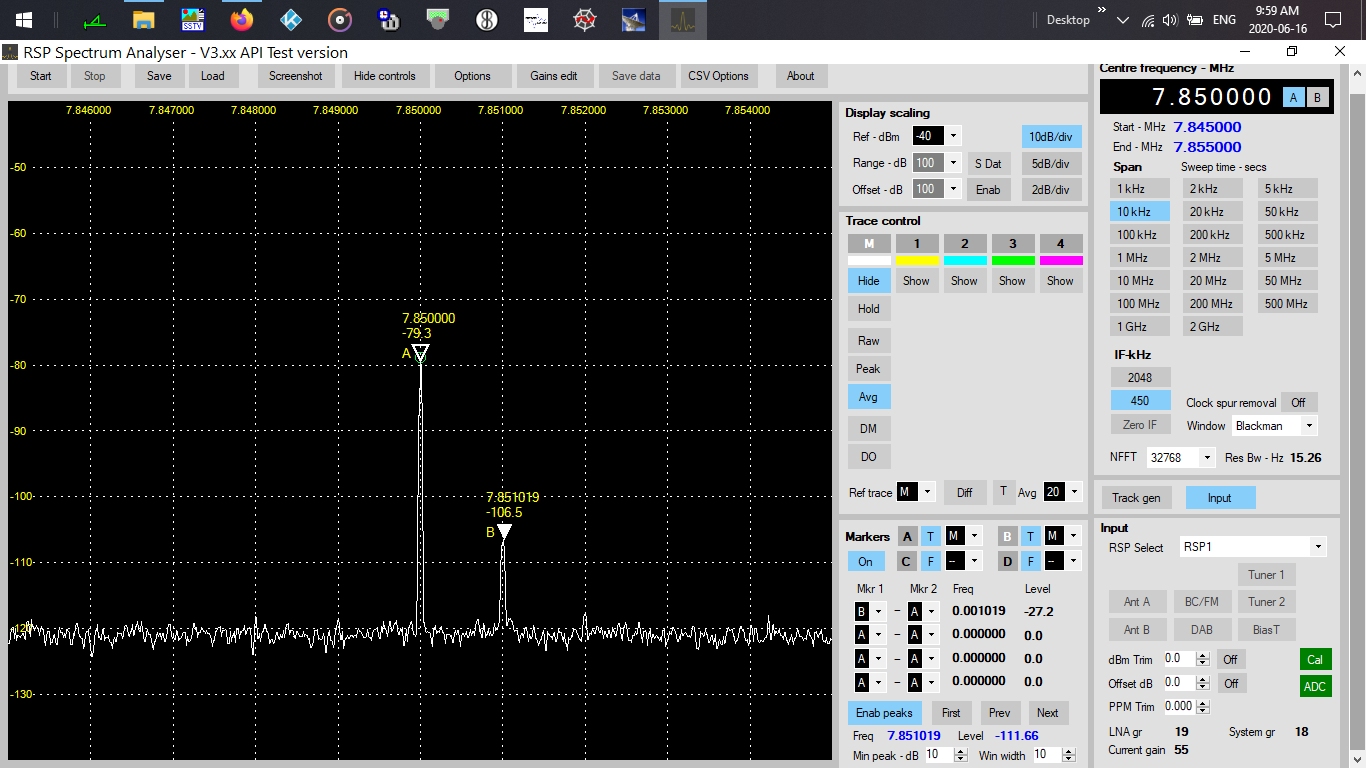
As you are aware, I am trying to measure an unknown frequency with accuracy.
When playing around, I use calibrated frequencies for CHU and WWV to guide my Markers.
In this particular screenshot we see that Marker A has found the sweet spot and is reading correctly.
Marker B however is reading a bit high. It should be 1,000 Hz high.Although CHU and WWV are calibrated sources, Doppler can cause their frequencies to shift at my receiver.
In my case, the interest is all about the Markers and their frequencies. I was initially thinking that your .csv dump spewed only the Marker data, but now I see (and understand) that it dumps all video buckets or all FFT bins. It sure would be nice to dump only the Marker data — either just one Marker, or all 4.
Perhaps you have a better method up your sleeve for what I am trying to do.
Regards,
DanAttachments:
June 17, 2020 at 12:43 am #1098Steve AndrewParticipantHi Dan
For improved resolution I would suggest increasing NFFT to 65536 or 131072, or even higher if required. At 450kHz IF and NFFT @ 262,144, the resolution bandwidth is reduced to 1.19Hz.
I would have thought Marker B should be spot on if you’ve selected marker B and used the next/prev buttons to move the marker to the required peak. Is this what you have done, but the marker is in error ? I’m pretty sure things will improve once you reduce the resolution bandwidth.
A bug has surfaced with regard to PPM Trim for a connected RSP device. Changing the value may cause the analyser to lock up. In addition, if the analyser tries to launch with a setting file where PPM is not zero, the analyser will not launch. You may have to manually edit the CurrentSettings.ini to SDR_PPM_Correction=0, or delete both Default.ini and CurrentSettings.ini
Let us know how you get on.
Best regards
Steve
June 23, 2020 at 12:36 pm #1119DanParticipantSteve:
Please see the attached screenshot.
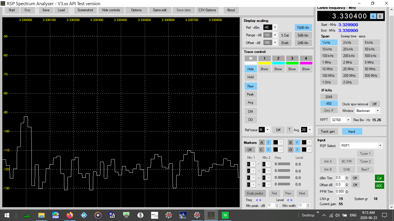
I was tuned to CHU on 3.330 MHz — but purposely dialed in 3.330400 on the Spectrum Analyser.
I then performed a data dump expecting to locate the CHU frequency using the dBm levels as a guide.
CHU clearly has the highest dBm level, but instead, after sorting the data dump, 3.330400 (+/-) shows the highest levels.18428 3.330462 -92.719
16358 3.330399 -94.174
18429 3.330462 -94.885
16357 3.330399 -97.466
18427 3.330462 -99.921
16359 3.330399 -100.366
10460 3.330219 -101.639
11275 3.330244 -102.257
9935 3.330203 -103.025It appears that the dialed in frequency in Spectrum Analyser slews the dBm levels.
Attachments:
June 23, 2020 at 12:55 pm #1121DanParticipantSteve:
See the attached screenshot.
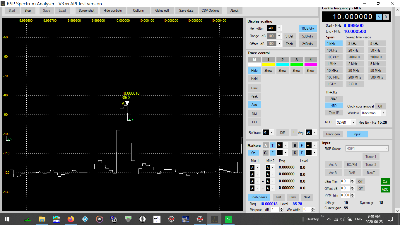
I am tuned to WWV and enabled the peaks. 3 of them appear (Marker A is covering one of them).
The issue is — the peaks appear on the SIDE of the desired frequency, and not in the CENTER.Marker A then tracks the offset peak and reads in error.
Attachments:
June 23, 2020 at 1:38 pm #1123DanParticipantSteve:
See the attached screenshot.
I am tuned to CHU, but offset the Spectrum Analyser dial frequency.I enabled Peaks and Marker A (it is covering one of the Peaks).
The visible (green bubble) Peak is in error. I presume it will report to the Data Dump in the same fashion.
The Data Dump will report the wrong dBm and the wrong frequency.It appears the Peak is not locating the highest value of dBm available.
Attachments:
June 23, 2020 at 2:09 pm #1125DanParticipantSteve:
Again, on behalf of the ham community (and others), thank you for this software.
Once I click the Markers ON, once I click the tracking ON, and once I click Enable Peaks ON …
1) Is there a way you can add to the Data Dump — Marker frequencies A, B, C, and D ?
2) Can you add to the precision of the Data Dump ? I would like to see milli-Hz (mHz).
3) On your somewhat busy video screen — once corrected, can you add the readout of the current Marker selected ? To milli-Hz value ?
Have fun,
Dan, VE9DANJune 23, 2020 at 3:22 pm #1126DanParticipantSteve:
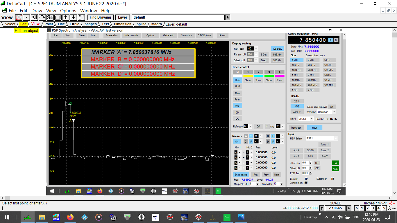
Here is what I am thinking for your video display.
See the screenshot. I use DeltaCad and Python 3.After all, a spectrum analyser is all about the frequency.
You can add the dBm level if desired.
Regards,
DanAttachments:
June 23, 2020 at 4:24 pm #1128ElsetDesaiParticipantHello…Gotten an opportunity to run this for an hour this arvo with my RSP1a from 12 MHz up to the 900MHz territory and chaos around with settings. This is a decent expansion to the becoming SDRplay stable.
June 24, 2020 at 7:01 am #1131Steve AndrewParticipantHi Dan
Thanks for your feedback. It will take me some time to work through the marker and peak positioning problems, as well as checking the CSV output. I’ll get back to you when I have something to report.
As far as milli-Hz resolution goes – I’m not sure I see the point as the resolution bandwidth, at best, is around 1Hz. At your current settings, your resolution bandwidth is too high at a bandwidth of 15Hz. As mentioned before, try increasing NFFT to something that gives you a higher resolution.
All the best
Steve
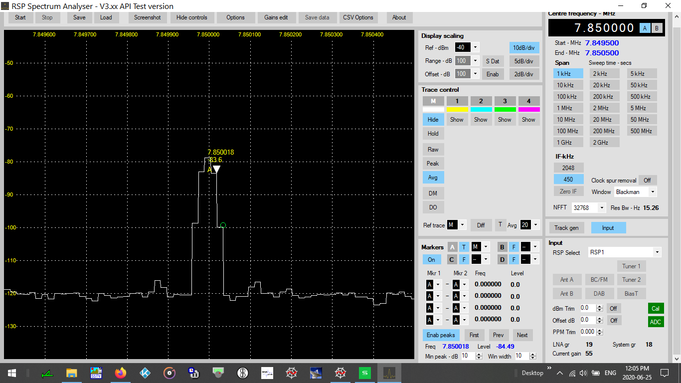
June 25, 2020 at 3:24 pm #1138DanParticipantSteve:
I was studying one of the Data Dumps.
See the attached screenshot from which the Dump was produced.
Ignore my settings for the moment — and look at my noise floor of roughly -120 dBm.Perhaps it is a function of your video display programming, but it seems to me that any data BELOW -120 dBm is superfluous and is of no interest.
Yet, the Dump contains a lot of data with dBm levels down to -160 dBm.
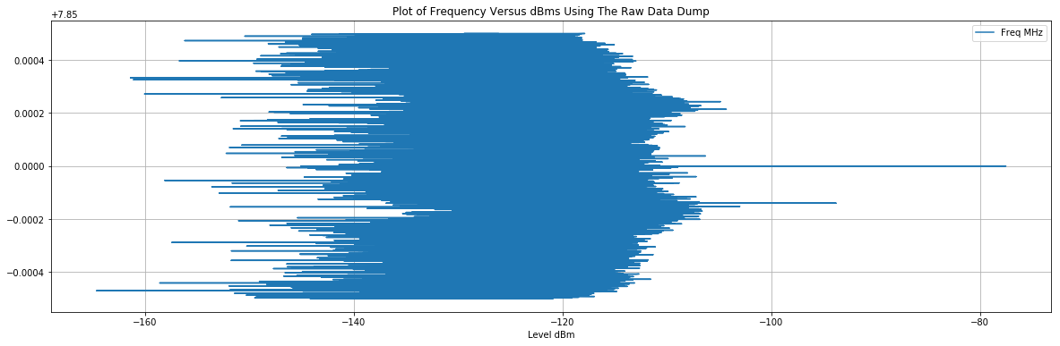
Check out my stupid sideways graph below. Easily one half (or more) of the Data Dump holds this superfluous data.
Any data left of -120 dBm on the X-axis is superfluous. -
AuthorPosts

- You must be logged in to reply to this topic.