SDRPlay Independent Community Forum › Forums › SDRPlay Devices › RSP1a – Hump and spikes in spectrum analyzer
- This topic has 3 replies, 3 voices, and was last updated by .
-
AuthorPosts
-
September 1, 2020 at 3:33 pm #1352RandyRParticipant
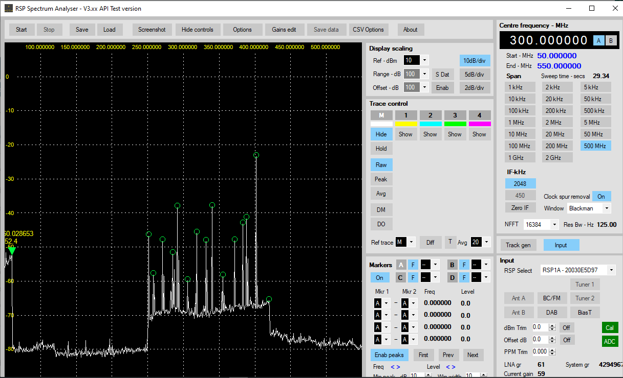
When using the Spectrum Analyzer with 300MHz as center frequency and a span of 500MHz, I’m seeing a 10dB “hump” in the noise floor with a lot of “spikes” up to 20-30dB above the noise floor between 250 and 400 MHz, which drops back down out to the high end of the scale even with the input to the RSP1a terminated with a 50 Ohm terminator. Is this a defective RSP1a, or is there some setting I’m missing. I’ve already turned on the “suppress clock spurs” option.
September 2, 2020 at 10:37 am #1363Andy2ParticipantHi Randy.
I get the same. The area from 250 to 400 MHz is very bumpy and there’s a very large spike at 401 MHz. It’s probably just a limitation in the design, as all the gubbins are crammed onto one small PCB and I don’t think there is any screening between the sections. It’s worth noting that that area of the spectrum relies on an extra mix, as the tuner chip in the RSPs does not normally cover it, so the uneven noise floor and those spikes may be a result of that.
For comparison, I have a Signal Hound SA44b specan. Apparently the previous ‘A’ version had a similar problem with clumps of spikes around certain frequencies, but further work produced the ‘B’ version with better RF layout and more screening and those spikes have almost disappeared into the noise floor. Mind you, the SA44b cost about 9 times the price of the SDRPlay units!September 3, 2020 at 1:38 pm #1367RandyRParticipantThanks for the info. This makes it almost unusable for what I wanted do to with it.
Attachments:
September 4, 2020 at 12:41 am #1371Steve AndrewParticipantHi Randy
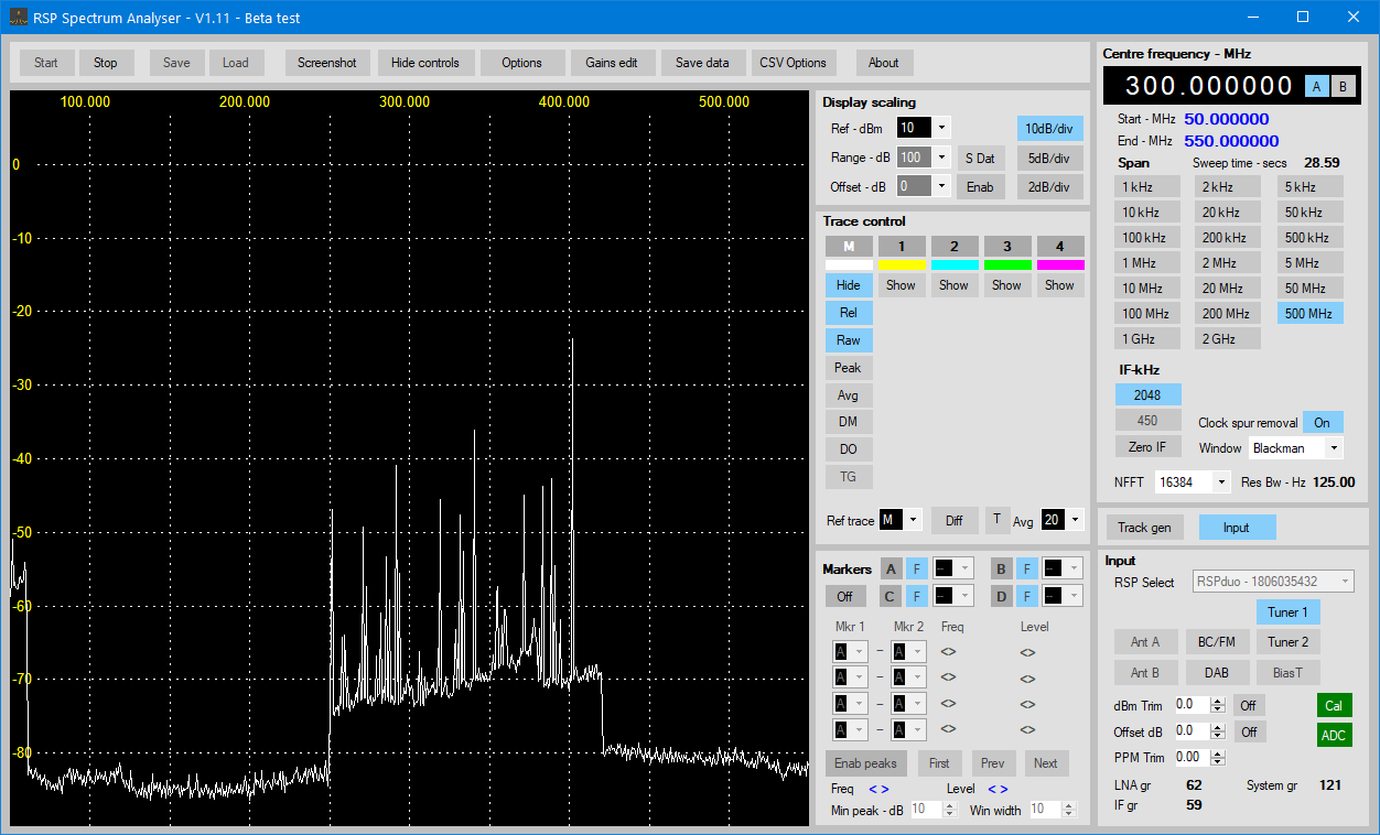
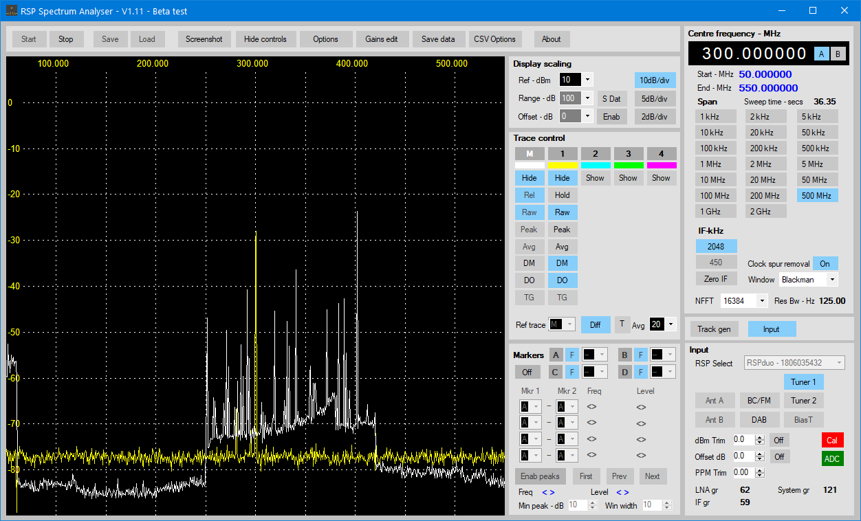
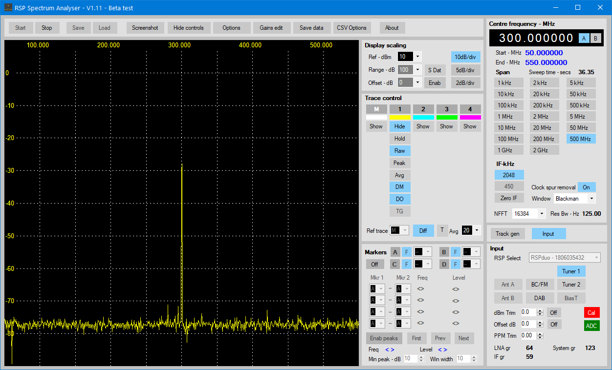
The humps are caused by band changes taking place within the RSP. Look at the gain tables editor to see the frequency limits for each band. The hump can also be affected by gain settings, set by the reference level. Dropping the ref level down to around -20 to -30dBm can help to reduce it. Do you need to have the ref level at 10dBm ?
If you want a clean trace as a baseline, try using differential mode with offset. Check the manual, pages 6 to 12. I’ve attached a few screen shots so you can see how it works.
Best regards
Steve
-
AuthorPosts

- You must be logged in to reply to this topic.